In this post, the second of a series on a floating-point FPGA limiter, we add support for stereo processing to our Limiter module and analyze its output by listening to a drum loop limited in our FPGA Audio Processor. If you haven’t already, make sure to check out the first part.
Stereo Limiting
The most significant change we are making to the Limiter module is adding support for processing both channels of our stereo audio. Architecturally speaking, there are many ways to approach this, depending on what we would like to optimize. In this case we would like to optimize for simplicity and easy of development, so we will take the FSM from the previous post and encapsulate it a separate ‘limiter_fsm’ module, which processes a single channel. We then instantiate the Limiter FSM once for each channel in the Limiter module, whose new description is shown below.
module limiter # (
parameter integer SP_FLOATING_POINT_BIT_WIDTH = 32
) (
input logic i_clock,
input logic i_enable,
// Audio Input
input logic i_data_valid,
input logic [SP_FLOATING_POINT_BIT_WIDTH-1 : 0] i_data_left,
input logic [SP_FLOATING_POINT_BIT_WIDTH-1 : 0] i_data_right,
// Controls
input logic [SP_FLOATING_POINT_BIT_WIDTH-1 : 0] i_linear_threshold,
// Audio Output
output logic o_data_valid,
output logic [SP_FLOATING_POINT_BIT_WIDTH-1 : 0] o_data_left,
output logic [SP_FLOATING_POINT_BIT_WIDTH-1 : 0] o_data_right
);
timeunit 1ns;
timeprecision 1ps;
logic data_valid;
logic [SP_FLOATING_POINT_BIT_WIDTH-1 : 0] data_left;
limiter_fsm # (
.SP_FLOATING_POINT_BIT_WIDTH (SP_FLOATING_POINT_BIT_WIDTH)
) limiter_fsm_left (
.i_clock (i_clock),
.i_enable (i_enable),
.i_data_valid (i_data_valid),
.i_data (i_data_left),
.i_linear_threshold (i_linear_threshold),
.o_data_valid (data_valid),
.o_data (data_left)
);
logic [SP_FLOATING_POINT_BIT_WIDTH-1 : 0] data_right;
limiter_fsm # (
.SP_FLOATING_POINT_BIT_WIDTH (SP_FLOATING_POINT_BIT_WIDTH)
) limiter_fsm_right (
.i_clock (i_clock),
.i_enable (i_enable),
.i_data_valid (i_data_valid),
.i_data (i_data_right),
.i_linear_threshold (i_linear_threshold),
.o_data (data_right)
);
always_comb begin
if (i_enable == 1'b1) begin
o_data_valid = data_valid;
o_data_left = data_left;
o_data_right = data_right;
end else begin
o_data_valid = i_data_valid;
o_data_left = i_data_left;
o_data_right = i_data_right;
end
end
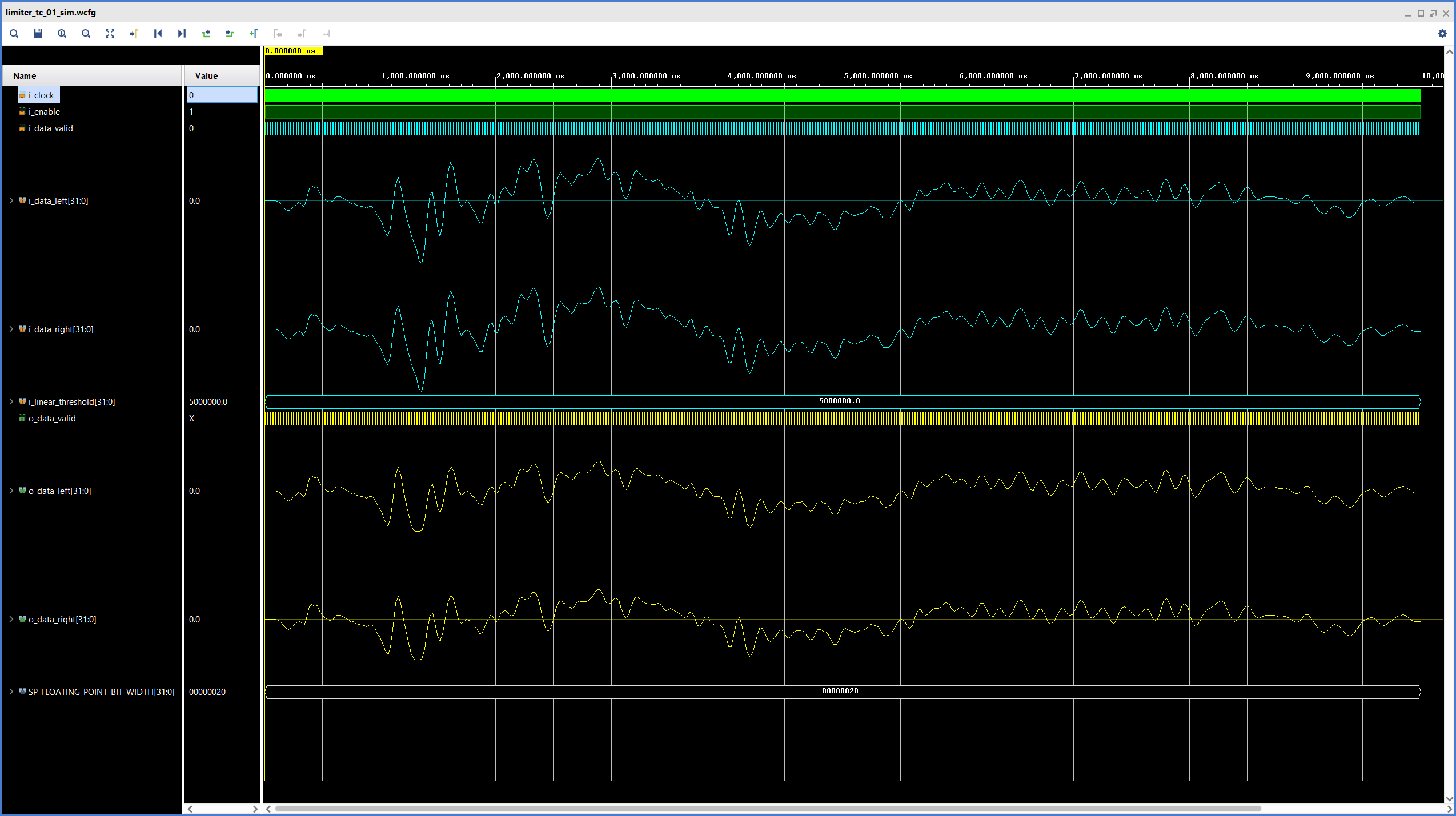
endmoduleThe figure below shows the results of the Limiter simulation, now with stereo support. We can see that our mono signal gets limited in the exact same way on both channels, just like we would expect.
Implementation
In addition to adding stereo support. we also update the instantiation of the Limiter in the Audio Processor to set the threshold value to 4.194.304, (~-6dBFS) and to connect the ‘i_enable’ signal to the SW2 switch on the ZedBoard. This will allow us to enable/disable the limiter in real time.
We can now run synthesis, implementation and bitstream generation. For this run I had to update the implementation settings to perform timing-oriented placement due to a setup violation in one of the Biquad Filter’s Floating-Point Operator IP cores. The resource utilization for the Limiter is shown in the figure below.
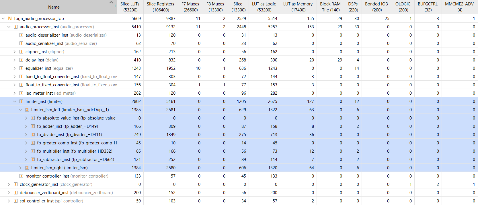
Our current Limiter implementation uses about 5% of the LUTs, Registers and DSP Slices available on the ZedBoard. A less naive implementation with resource sharing across audio channels could easily reduce the utilization by 30% or 40%.
Audio Samples
Up until now we have always checked the simulation results using waveforms. This can be very revealing and we will continue to do it, but since we are discussing audio processing, it would be nice to have some clips to show what our FPGA Audio Processor can do.
My setup for developing and testing includes my laptop, an iD22 audio interface from Audient, and the ZedBoard. I am able to route the audio from my PC to the secondary analog output of my iD22 (the main output is connected to my loudspeakers), which in turns is connected to the Line In input of the ZedBoard. The audio processed by the FPGA goes out of the ZedBoard’s Line Out connector and into the balanced inserts of the iD22.
The figure below shows the setup that I used in Cubase, my Digital Audio Workstation (DAW), to play the sample audio, capture the output of the FPGA Audio Processor and analyze the results.
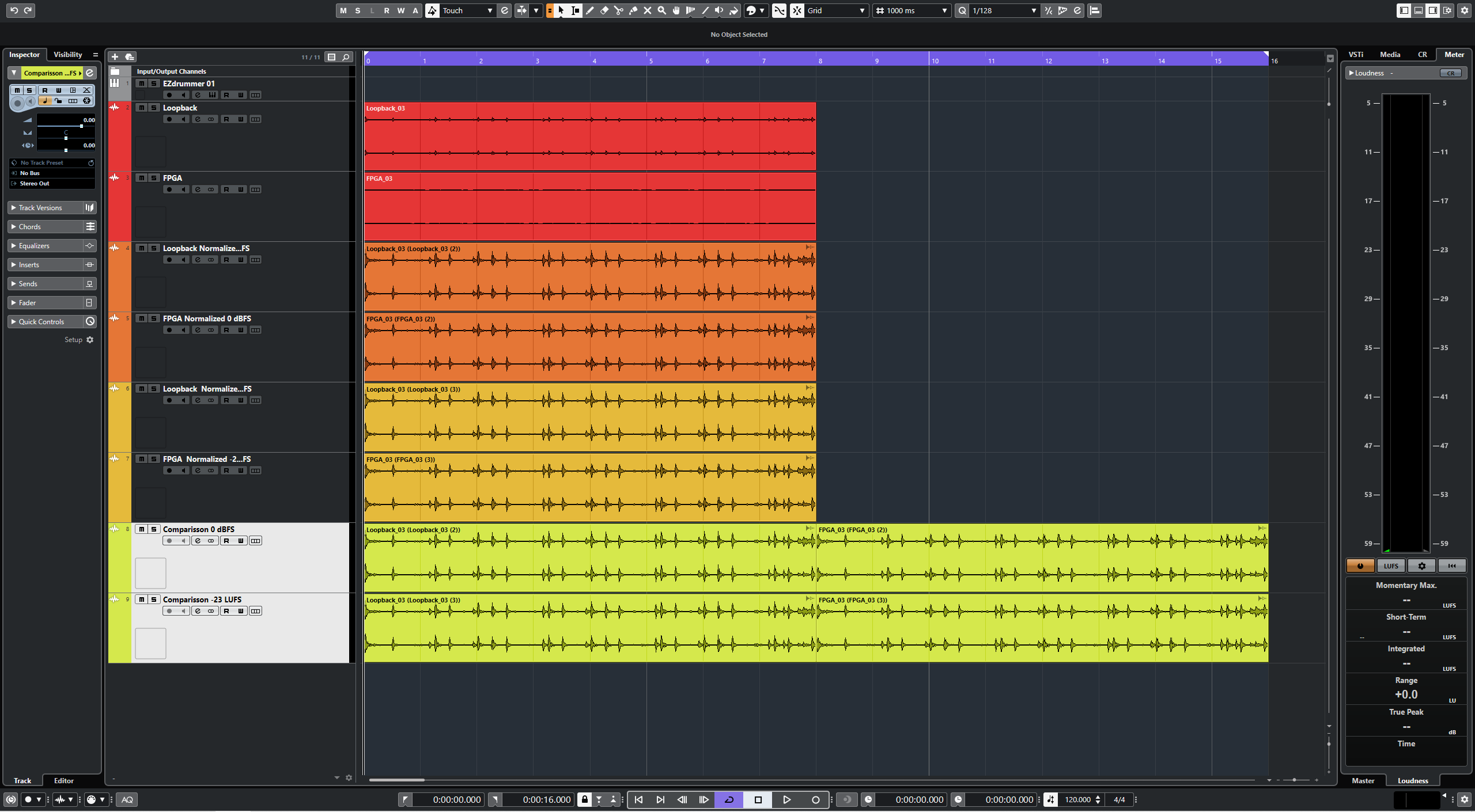
As test signal I’m using an 8-bar drum loop generated by a virtual instrument. I record the drum loop back into the first audio track and simultaneously record the output of the FPGA with the Limiter enabled in the second audio track. The third and fourth audio tracks contain respectively the original loop and the FPGA output normalized so that the highest sample value in each one is 0 dBFS. The fourth and fifth audio tracks contain respectively the original loop and the FPGA output normalized to a loudness of -23 LUFS. The last two tracks are only used for combining the normalized audio so we can listen to it back-to-back.
The most revealing comparison is with the files normalized so that they both peak at 0 dBFS. The first half of the audio clip has the original loop, the second half has the output of our Limiter. Have a listen:
This is probably the most common use of a limiter in an audio production setting: by reducing the amplitude of the transients we are able to increase the perceived loudness of the audio clip. The downside of this strategy in a musical context is that we lose dynamic range, especially in percussive elements. To check whether that might be the case in our test, here’s the same comparison, but normalized so that they have the same loudness (-23 LUFS):
As far as I can tell, there is no major loss of transient information in the limited clip. Having said that, this test is less robust than the peak normalization. The perceived loss of transients is highly subjective, the files I uploaded here are compressed (MP3, 320 Kbps), and the limiting was not that aggressive to begin with. I’m already exploring ways to streamline a more robust setup for this type of analysis in the future.
In the next and final installment of this series we will add lookahead functionality to our Limiter. See you then!
Cheers,
Isaac
All files for this post are available in the FPGA Audio Processor repository under this tag.