In this post we start a series in which we will explore the RTL description and simulation of a floating-point Limiter for our FPGA Audio Processor.
Our Audio Processor already includes a delay and a single-band equalizer. The delay belongs to the family of time-based effects, while the equalizer is part of the frequency-based effects. Today start our exploration of a new kind of audio effect: dynamic range controllers (DRC). The most common DRC effects are gates, compressors, expanders, and the subject of today’s post, limiters.
What is a Limiter?
A limiter aims to reduce the dynamic range of the signal above a certain threshold, but to otherwise change the signal as little as possible (ideally not at all!). Whenever the input signal goes above the limiting threshold, the limiter kicks in and applies a gain smaller than one to reduce the amplitude of the samples above the threshold. When the input signal comes back down below the threshold, the limiter stops applying its gain and simply passes the incoming signals through to the output.
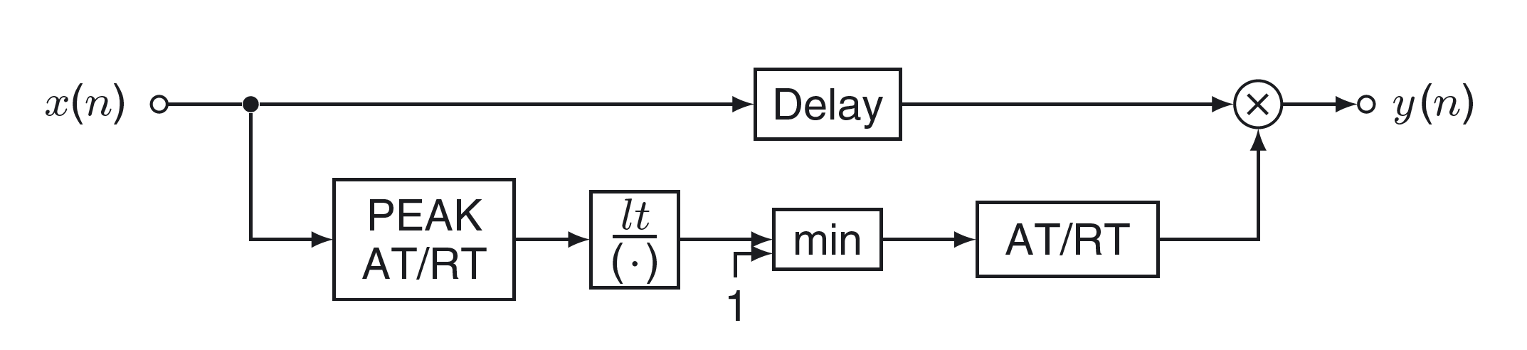
The figure below shows the block diagram of a limiter, as described in Udo Zölzer’s DAFX Digital Audio Effects (Second Edition).
RTL Description of the Limiter
We will use the code from the source above as a reference, so our Limiter will be a single-precision floating-point FPGA implementation of the algorithm described in the book’s sample code. The book also references the Dynamic range control of digital audio signals paper from the BBC research engineer G. W. McNally, especially when it comes to the attack and release time filter for the envelope detection and gain smoothing.
Diving into the details of how a limiter works is outside the scope of this post, so I kindly refer you to the sources above if you would like to learn more about that. I’m also choosing not to reproduce the book’s sample code here because I’m guessing it might be problematic from a copyright perspective. This is not ideal, but I hope it will serve as an incentive to get the book, as it is a great resource for digital audio processing.
Our limiter performs the following main tasks:
- Calculate the envelope of the incoming signal by extracting the absolute value of each sample and smoothing it over time. The time smoothing uses different coefficients depending on whether the incoming sample is above or below the threshold for limiting. In the former case the release time is used, in the latter the attack time is used (this is carried out in the ‘PEAK AT/RT‘ block in the figure above)
- Calculate the required gain by comparing the value of the envelope to the threshold. Here too attack and release time coefficients are used to smooth the gain adjustment (this is carried out in the three remaining blocks of the lower path in the figure above)
- Apply the calculated gain to the input sample to generate the output. The calculation of the output samples can be delayed so that the gain can account for future changes in the incoming signals. This delay is also known as lookahead (this is carried out in the upper path in the figure above)
The RTL description of the limiter follows the now familiar pattern of an FSM executing all the calculations by driving the floating-point operation IP cores. As in previous modules, we used a naive description, with each operation being executed sequentially and one instance of the floating-point IP core for each type of operation.
This is the most complex module we have implemented so far, which is evident by the number of states in the FSM. It shows that, for moderately complex algorithms and some parallelism, this approach might result in large, complex state machines which might be difficult to maintain, debug and expand.
The complete source code for the Limiter module is shown below. In this version only the left channel is processed, and all the logic is contained in a single module. This was done as a quick way to verify the basic functionality, stereo support will be added next.
module limiter # (
parameter integer SP_FLOATING_POINT_BIT_WIDTH = 32
) (
input logic i_clock,
input logic i_enable,
// Audio Input
input logic i_data_valid,
input logic [SP_FLOATING_POINT_BIT_WIDTH-1 : 0] i_data_left,
input logic [SP_FLOATING_POINT_BIT_WIDTH-1 : 0] i_data_right,
// Controls
input logic [SP_FLOATING_POINT_BIT_WIDTH-1 : 0] i_linear_threshold,
// Audio Output
output logic o_data_valid,
output logic [SP_FLOATING_POINT_BIT_WIDTH-1 : 0] o_data_left,
output logic [SP_FLOATING_POINT_BIT_WIDTH-1 : 0] o_data_right
);
timeunit 1ns;
timeprecision 1ps;
parameter logic [SP_FLOATING_POINT_BIT_WIDTH-1 : 0] ATTACK_TIME = 32'h3F666666; // 0.9
parameter logic [SP_FLOATING_POINT_BIT_WIDTH-1 : 0] RELEASE_TIME = 32'h3E99999A; // 0.3
logic [SP_FLOATING_POINT_BIT_WIDTH-1 : 0] data_left;
logic [SP_FLOATING_POINT_BIT_WIDTH-1 : 0] data_right;
logic [SP_FLOATING_POINT_BIT_WIDTH-1 : 0] xpeak;
logic [SP_FLOATING_POINT_BIT_WIDTH-1 : 0] gain;
logic [SP_FLOATING_POINT_BIT_WIDTH-1 : 0] coefficient;
logic [SP_FLOATING_POINT_BIT_WIDTH-1 : 0] filter;
logic [SP_FLOATING_POINT_BIT_WIDTH-1 : 0] absolute_value;
logic fp_abs_value_valid_in;
logic [SP_FLOATING_POINT_BIT_WIDTH-1 : 0] fp_abs_value_data_in;
logic fp_abs_value_valid_out;
logic [SP_FLOATING_POINT_BIT_WIDTH-1 : 0] fp_abs_value_data_out;
fp_absolute_value fp_absolute_value_inst (
.s_axis_a_tvalid (fp_abs_value_valid_in),
.s_axis_a_tdata (fp_abs_value_data_in),
.m_axis_result_tvalid (fp_abs_value_valid_out),
.m_axis_result_tdata (fp_abs_value_data_out)
);
logic fp_greater_comp_valid_in;
logic [SP_FLOATING_POINT_BIT_WIDTH-1 : 0] fp_greater_comp_data_a_in;
logic [SP_FLOATING_POINT_BIT_WIDTH-1 : 0] fp_greater_comp_data_b_in;
logic fp_greater_comp_valid_out;
logic [7 : 0] fp_greater_comp_data_out;
fp_greater_comp fp_greater_comp_inst (
.aclk (i_clock),
.s_axis_a_tvalid (fp_greater_comp_valid_in),
.s_axis_a_tdata (fp_greater_comp_data_a_in),
.s_axis_b_tvalid (fp_greater_comp_valid_in),
.s_axis_b_tdata (fp_greater_comp_data_b_in),
.m_axis_result_tvalid (fp_greater_comp_valid_out),
.m_axis_result_tdata (fp_greater_comp_data_out)
);
logic fp_subtractor_valid_in;
logic [SP_FLOATING_POINT_BIT_WIDTH-1 : 0] fp_subtractor_data_a_in;
logic [SP_FLOATING_POINT_BIT_WIDTH-1 : 0] fp_subtractor_data_b_in;
logic fp_subtractor_valid_out;
logic [SP_FLOATING_POINT_BIT_WIDTH-1 : 0] fp_subtractor_data_out;
fp_subtractor fp_subtractor_inst (
.aclk (i_clock),
.s_axis_a_tvalid (fp_subtractor_valid_in),
.s_axis_a_tdata (fp_subtractor_data_a_in),
.s_axis_b_tvalid (fp_subtractor_valid_in),
.s_axis_b_tdata (fp_subtractor_data_b_in),
.m_axis_result_tvalid (fp_subtractor_valid_out),
.m_axis_result_tdata (fp_subtractor_data_out)
);
logic fp_mult_valid_in;
logic [SP_FLOATING_POINT_BIT_WIDTH-1 : 0] fp_mult_data_in_a;
logic [SP_FLOATING_POINT_BIT_WIDTH-1 : 0] fp_mult_data_in_b;
logic fp_mult_valid_out;
logic [SP_FLOATING_POINT_BIT_WIDTH-1 : 0] fp_mult_data_out;
fp_multiplier fp_multiplier_inst (
.aclk (i_clock),
.s_axis_a_tvalid (fp_mult_valid_in),
.s_axis_a_tdata (fp_mult_data_in_a),
.s_axis_b_tvalid (fp_mult_valid_in),
.s_axis_b_tdata (fp_mult_data_in_b),
.m_axis_result_tvalid (fp_mult_valid_out),
.m_axis_result_tdata (fp_mult_data_out)
);
logic fp_adder_valid_in;
logic [SP_FLOATING_POINT_BIT_WIDTH-1 : 0] fp_adder_data_in_a;
logic [SP_FLOATING_POINT_BIT_WIDTH-1 : 0] fp_adder_data_in_b;
logic fp_adder_valid_out;
logic [SP_FLOATING_POINT_BIT_WIDTH-1 : 0] fp_adder_data_out;
fp_adder fp_adder_inst (
.aclk (i_clock),
.s_axis_a_tvalid (fp_adder_valid_in),
.s_axis_a_tdata (fp_adder_data_in_a),
.s_axis_b_tvalid (fp_adder_valid_in),
.s_axis_b_tdata (fp_adder_data_in_b),
.m_axis_result_tvalid (fp_adder_valid_out),
.m_axis_result_tdata (fp_adder_data_out)
);
logic fp_divider_valid_in;
logic [SP_FLOATING_POINT_BIT_WIDTH-1 : 0] fp_divider_data_in_a;
logic [SP_FLOATING_POINT_BIT_WIDTH-1 : 0] fp_divider_data_in_b;
logic fp_divider_valid_out;
logic [SP_FLOATING_POINT_BIT_WIDTH-1 : 0] fp_divider_data_out;
fp_divider fp_divider_inst (
.aclk (i_clock),
.s_axis_a_tvalid (fp_divider_valid_in),
.s_axis_a_tdata (fp_divider_data_in_a),
.s_axis_b_tvalid (fp_divider_valid_in),
.s_axis_b_tdata (fp_divider_data_in_b),
.m_axis_result_tvalid (fp_divider_valid_out),
.m_axis_result_tdata (fp_divider_data_out)
);
typedef enum logic [5 : 0] {IDLE,
WAIT_SAMPLE,
GET_ABS_VALUE,
COMPARE_XPEAK,
CALC_XPEAK_1,
CALC_XPEAK_2,
CALC_XPEAK_3,
CALC_XPEAK_4,
THRESHOLD_XPEAK_RATIO,
CALC_FILTER,
COMPARE_FILTER,
COMPARE_FILTER_GAIN,
CALC_GAIN_1,
CALC_GAIN_2,
CALC_GAIN_3,
CALC_GAIN_4,
CALC_OUTPUT,
DRIVE_OUTPUT} limiter_fsm_state_t;
limiter_fsm_state_t limiter_fsm_state = IDLE;
logic [SP_FLOATING_POINT_BIT_WIDTH-1 : 0] aux;
always_ff @(posedge i_clock) begin
case (limiter_fsm_state)
IDLE : begin
xpeak <= 32'h00000000;
gain <= 32'h3F800000;
fp_abs_value_valid_in <= 1'b0;
fp_greater_comp_valid_in <= 1'b0;
fp_subtractor_valid_in <= 1'b0;
fp_mult_valid_in <= 1'b0;
fp_adder_valid_in <= 1'b0;
fp_divider_valid_in <= 1'b0;
o_data_valid <= 1'b0;
data_left <= 32'h00000000;
data_right <= 32'h00000000;
if (i_enable == 1'b1) begin
limiter_fsm_state <= WAIT_SAMPLE;
end
end
WAIT_SAMPLE : begin
o_data_valid <= 1'b0;
if (i_data_valid == 1'b1) begin
data_left <= i_data_left;
data_right <= i_data_right;
fp_abs_value_data_in <= i_data_left;
fp_abs_value_valid_in <= 1'b1;
limiter_fsm_state <= GET_ABS_VALUE;
end
end
GET_ABS_VALUE : begin
fp_abs_value_valid_in <= 1'b0;
if (fp_abs_value_valid_out == 1'b1) begin
absolute_value <= fp_abs_value_data_out;
fp_greater_comp_data_a_in <= fp_abs_value_data_out;
fp_greater_comp_data_b_in <= xpeak;
fp_greater_comp_valid_in <= 1'b1;
limiter_fsm_state <= COMPARE_XPEAK;
end
end
COMPARE_XPEAK : begin
fp_greater_comp_valid_in <= 1'b0;
if (fp_greater_comp_valid_out == 1'b1) begin
if (fp_greater_comp_data_out[0] == 1'b1) begin
coefficient <= ATTACK_TIME;
end else begin
coefficient <= RELEASE_TIME;
end
limiter_fsm_state <= CALC_XPEAK_1;
end
end
CALC_XPEAK_1 : begin
fp_subtractor_valid_in <= 1'b1;
fp_subtractor_data_a_in <= 32'h3F800000;
fp_subtractor_data_b_in <= coefficient;
limiter_fsm_state <= CALC_XPEAK_2;
end
CALC_XPEAK_2 : begin
fp_subtractor_valid_in <= 1'b0;
if (fp_subtractor_valid_out == 1'b1) begin
fp_mult_valid_in <= 1'b1;
fp_mult_data_in_a <= fp_subtractor_data_out;
fp_mult_data_in_b <= xpeak;
limiter_fsm_state <= CALC_XPEAK_3;
end
end
CALC_XPEAK_3 : begin
fp_mult_valid_in <= 1'b0;
if (fp_mult_valid_out == 1'b1) begin
aux <= fp_mult_data_out;
fp_mult_valid_in <= 1'b1;
fp_mult_data_in_a <= coefficient;
fp_mult_data_in_b <= absolute_value;
limiter_fsm_state <= CALC_XPEAK_4;
end
end
CALC_XPEAK_4 : begin
fp_mult_valid_in <= 1'b0;
if (fp_mult_valid_out == 1'b1) begin
fp_adder_valid_in <= 1'b1;
fp_adder_data_in_a <= aux;
fp_adder_data_in_b <= fp_mult_data_out;
limiter_fsm_state <= THRESHOLD_XPEAK_RATIO;
end
end
THRESHOLD_XPEAK_RATIO : begin
fp_adder_valid_in <= 1'b0;
if (fp_adder_valid_out) begin
xpeak <= fp_adder_data_out;
fp_divider_valid_in <= 1'b1;
fp_divider_data_in_a <= i_linear_threshold;
fp_divider_data_in_b <= fp_adder_data_out;
limiter_fsm_state <= CALC_FILTER;
end
end
CALC_FILTER : begin
fp_divider_valid_in <= 1'b0;
if (fp_divider_valid_out == 1'b1) begin
filter <= fp_divider_data_out;
fp_greater_comp_valid_in <= 1'b1;
fp_greater_comp_data_a_in <= fp_divider_data_out;
fp_greater_comp_data_b_in <= 32'h3F800000;
limiter_fsm_state <= COMPARE_FILTER;
end
end
COMPARE_FILTER : begin
fp_greater_comp_valid_in <= 1'b0;
if (fp_greater_comp_valid_out == 1'b1) begin
if (fp_greater_comp_data_out[0] == 1'b1) begin
filter <= 32'h3F800000;
fp_greater_comp_data_b_in <= 32'h3F800000;
end else begin
fp_greater_comp_data_b_in <= filter;
end
fp_greater_comp_valid_in <= 1'b1;
fp_greater_comp_data_a_in <= gain;
limiter_fsm_state <= COMPARE_FILTER_GAIN;
end
end
COMPARE_FILTER_GAIN : begin
fp_greater_comp_valid_in <= 1'b0;
if (fp_greater_comp_valid_out == 1'b1) begin
if (fp_greater_comp_data_out[0] == 1'b1) begin
coefficient <= ATTACK_TIME;
end else begin
coefficient <= RELEASE_TIME;
end
limiter_fsm_state <= CALC_GAIN_1;
end
end
CALC_GAIN_1 : begin
fp_subtractor_valid_in <= 1'b1;
fp_subtractor_data_a_in <= 32'h3F800000;
fp_subtractor_data_b_in <= coefficient;
limiter_fsm_state <= CALC_GAIN_2;
end
CALC_GAIN_2 : begin
fp_subtractor_valid_in <= 1'b0;
if (fp_subtractor_valid_out == 1'b1) begin
fp_mult_valid_in <= 1'b1;
fp_mult_data_in_a <= fp_subtractor_data_out;
fp_mult_data_in_b <= gain;
limiter_fsm_state <= CALC_GAIN_3;
end
end
CALC_GAIN_3 : begin
fp_mult_valid_in <= 1'b0;
if (fp_mult_valid_out == 1'b1) begin
aux <= fp_mult_data_out;
fp_mult_valid_in <= 1'b1;
fp_mult_data_in_a <= coefficient;
fp_mult_data_in_b <= filter;
limiter_fsm_state <= CALC_GAIN_4;
end
end
CALC_GAIN_4 : begin
fp_mult_valid_in <= 1'b0;
if (fp_mult_valid_out == 1'b1) begin
fp_adder_valid_in <= 1'b1;
fp_adder_data_in_a <= aux;
fp_adder_data_in_b <= fp_mult_data_out;
limiter_fsm_state <= CALC_OUTPUT;
end
end
CALC_OUTPUT : begin
fp_adder_valid_in <= 1'b0;
if (fp_adder_valid_out == 1'b1) begin
gain <= fp_adder_data_out;
fp_mult_valid_in <= 1'b1;
fp_mult_data_in_a <= fp_adder_data_out;
fp_mult_data_in_b <= data_left;
limiter_fsm_state <= DRIVE_OUTPUT;
end
end
DRIVE_OUTPUT : begin
fp_mult_valid_in <= 1'b0;
if (fp_mult_valid_out == 1'b1) begin
o_data_valid <= 1'b1;
o_data_left <= fp_mult_data_out;
o_data_right <= data_right;
limiter_fsm_state <= WAIT_SAMPLE;
end
end
default : begin
limiter_fsm_state <= IDLE;
end
endcase
end
endmoduleLimiter Simulation
We run the simulation by using our testbench with the SystemVerilog WAVE file reader and the script for standalone simulation with Vivado as a starting point. The testbench can be used as-is, we only need to instantiate the Limiter module. The simulation script must be expanded to include all the floating-point IP cores used by the Limiter. We used our familiar snare hit as the input and run the simulation for 10 ms. The resulting waveforms are shown in figure below.
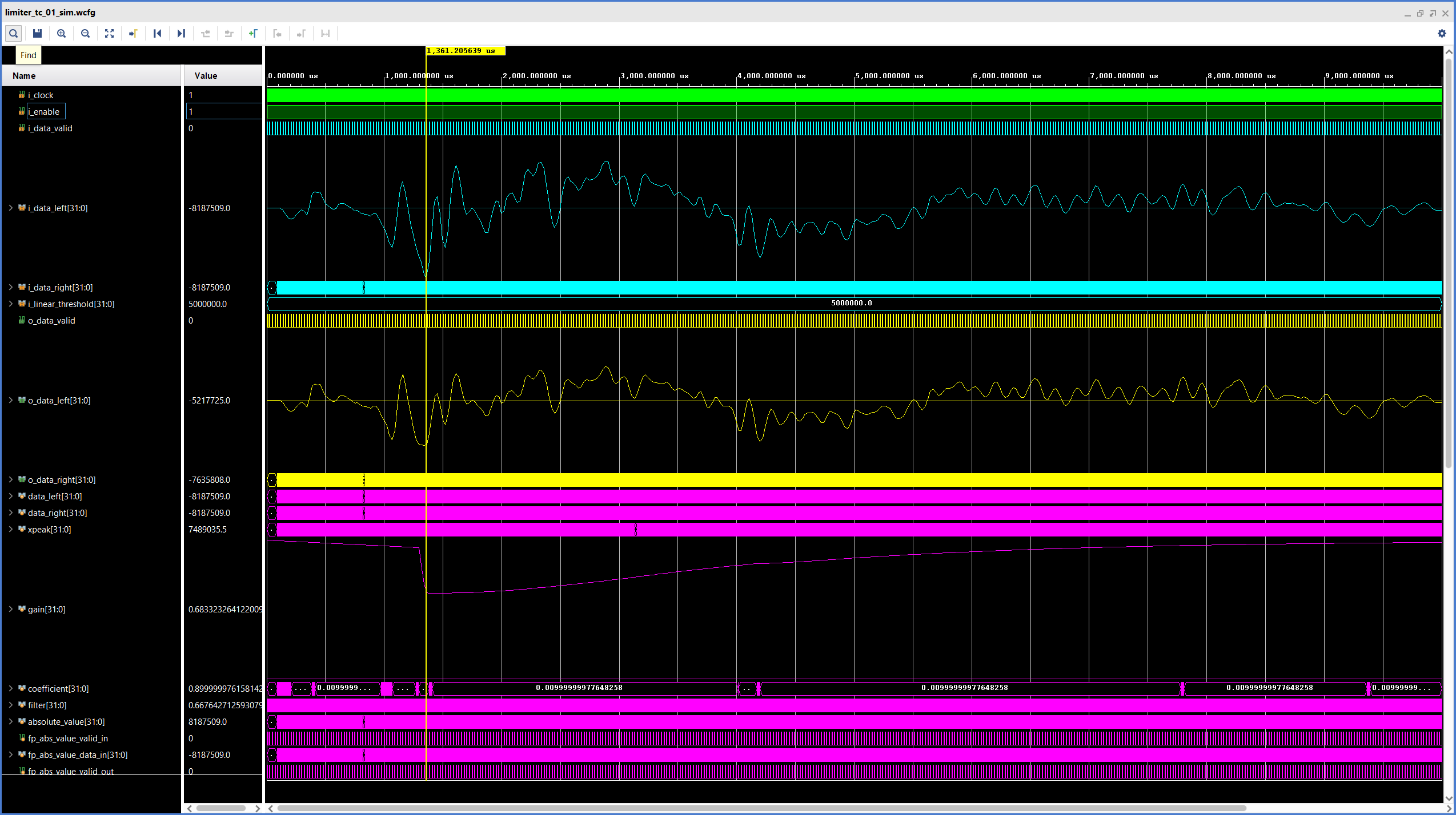
For this simulation the limiting threshold was set to 5.000.000 in the linear scale. the three analog waveforms in Figure 2 are, from top to bottom, the left channel input, the left channel output, and the gain of the Limiter. The latency of our Limiter is 60 cycles.
We can see that, for the first few milliseconds of the simulation, the output of the Limiter is equal to its input, and the gain remains equal to 1. The misleading downward slope in the gain signal at the beginning of the simulation is due to how the Vivado simulator draws ‘analog’ waveforms, the gain actually stays at ‘1’ until the first inflexion point.
At ~1.3 ms, where the marker is located, the input signal reaches its highest absolute value, close to the maximum value that can be represented by a 24-bit signed integer. We can clearly see that by this point the limiter has already kicked in, so the output value is much lower than that. This is also the time where the gain reaches its lowest value, which is exactly the behavior we would like to see in a limiter.
For this simulation we are using fast attack and slow release times, which means that the Limiter kicks in and reduces its gain very quickly after the threshold has been exceeded, but then takes a long time before setting the gain back to unity after the input signal is again below the threshold. Different combinations of attack and release time values will yield different audible results depending on the input signal.
Finally, we see that the highest absolute value of the output signal (5.217.725) is above the threshold we selected (5.000.000). This is not an ideal behavior, but it is expected (and not completely avoidable in our current implementation), even McNally noted this could happen. He suggests using a delay to give the detection logic time to react to the changes in the incoming signal and prevent these peaks from getting through the limiter. We might explore this in a later post.
In the next installment of this series we will add stereo support, discuss the implementation results, and listen to some audio samples to hear our limiter in action. Stay tuned!
Cheers,
Isaac
All files for this post are available in the FPGA Audio Processor repository under this tag.
8 responses to “029 – Floating-Point FPGA Audio Limiter (1)”
Thanks for posting this – it looks very interesting. I opened the project in Vivado 2020.2 and was able to run through implementation, saw timing was met, and generate a bitstream. However, when I tried behavioral simlation, I received the following error:
[XSIM 43-3225] Cannot find design unit xil_defaultlib.tc_01 in library work located at xsim.dir/work.
Have you encountered this before, or know of a resolution? Thought I would check in before trying to resolve this myself.
Thanks
John
Hi John,
I just cloned a fresh copy of the repository to a different location on my PC, and the simulation runs without issues.
How are you starting the simulation? It is meant to be run in batch mode, so you would need to go to the simulation folder (fpga_audio_processor\sim\limiter\tc_01), open a terminal windows and type: ‘vivado -mode batch -source sim.tcl’ (without quotes, and assuming your environment variable has been set properly).
Hope this helps!
Cheers,
Isaac
Hi Isaac,
Yes, I was running the Vivado GUI when I got the simulation error. Switching to batch mode allowed simulation to complete.
However, when the xsim viewer was launched with the waveform config file and the waveform database file, I can see all the signal names listed in the waveform viewer, but there are no waveforms. I checked my log files and didn’t see any errors, just a warning that I don’t think is related to this issue. Here is my TCL console log from the xsim GUI:
open_wave_database limiter_tc_01_sim.wdb
WARNING: [Board 49-91] Board repository path ‘c:/trd_home/vivado/zcu102_base_trd/hw_platform/board’ does not exist, it will not be used to search board files.
INFO: [IP_Flow 19-234] Refreshing IP repositories
INFO: [IP_Flow 19-1704] No user IP repositories specified
INFO: [IP_Flow 19-2313] Loaded Vivado IP repository ‘C:/Xilinx/Vivado/2020.2/data/ip’.
open_wave_config C:/designs/Biamp/aaron_fp_limiter/fpga_audio_processor-029-floating-point-fpga-audio-limiter-1/sim/limiter/tc_01/limiter_tc_01_sim.wcfg
Any ideas why the waveforms aren’t showing? Do you think it has to do with the warning about the board repository path?
Thanks for your assistance,
John
Hi John,
could you please check that the Vivado Waveform Database File (limiter_tc_01_sim.wdb) is generated correctly? It should be stored directly in the simulation directory and take up about 9 MB.
If the file is there you should be able to open it by launching the Vivado GUI and, from the start screen (without opening the project) going to ‘Flow -> Open Static Simulation’. Once the database is open you can load the Waveform Configuration File from ‘File -> Simulation Waveform -> Open Configuration…’
If you can go through the steps above, it means that the simulation ran correctly. I’m not sure why it dosn’t work right away.
One more thing: if you would like to have the exact same behavior of the Limiter as in the waveform shown in the blog post, you’d have to change the release time to 0.01 (32’h3C23D70A).
Let me know if this works!
Cheers,
Isaac
Not sure what happened with the giant font in the previous comment. It should have appears like this:
open_wave_database limiter+tc_01_sim.wdb
Apparently the hash (pound sign) symbol in front of the open_wave_database commands causes the fon to change size. Wierd.
HI Isaac,
I found the issue – in the file fpga_audio_processor-029-floating-point-fpga-audio-limiter-1\sim\common\wave_file_reader.sv, there is a hard-coded directory path on line 52. This is the $fopen command to read the snare.wav file. I changed the path to match my machine, and everything works as expected.
Thanks!
Hi John,
thanks for working on this – and letting me know what the problem was. The fix will be available in Tag 032.
Cheers,
Isaac