In this post we start a series wich will explore the implementation of an FPGA double-precision floating-point Biquad Filter as the basis for an Equalizer in our ZedBoard Audio Processor. In the first installment we will introduce the Biquad Filter, discuss the supporting modules required by our architecture and set up the simulation environment for our Equalizer.
Biquad Filter
We will use the Direct Form II Transposed Structure of the Biquad Filter as the core element of our Equalizer. The block diagram of our Biquad Filter is shown in the figure below.
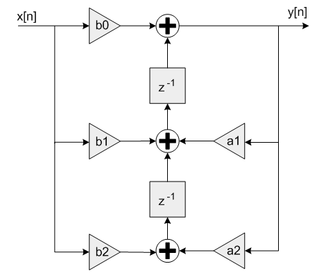
As we can see, the Biquad is an Infinite Impulse Response (IIR) filter, which means that each new output sample depends on both current and past input values, as well as on past output values (and filter coefficients). The other main type of filter is the Finite Impulse Response (FIR) filter, in which the new output samples depend only on current and past input values (and filter coefficients).
IIR filters have advantages and disadvantages when compared to FIR filters. One important advantage of IIR filters is that they can achieve good performance with a relatively low number of coefficients and operations, which makes them well-suited to real-time applications. On the other hand, one crucial disadvantage is that they can become unstable, which can cause sustained oscillations or momentary spikes in our output signal.
One reason an IIR filter can become unstable is if our implementation lacks the resolution to represent the coefficients with enough accuracy. To help mitigate this we will use double precision floating point representation for the samples and filter coefficients in our equalizer. We can do this by converting the audio samples from single to double precision before the Biquad module and from double to single precision after the Biquad module without having to make changes to our processing pipeline elsewhere.
Finally, a Biquad filter can be configured to perform any operation required by a parametric equalizer: low/high pass, low/high shelf, bandpass, notch and peak. We can do this by calculating the filter coefficients for the desired sample rate, cut-off frequency, Q-factor and gain. We will use Ear Level Engineering’s calculator to generate the coefficients, and I strongly recommend you check out the other resources on their website, including their description of Biquads.
Equalizer Architecture
Our equalizer will consist of three modules:
- One single- to double-precision floating-point converter module
- One Biquad Filter module
- One double- to single-precision floating-point converter module
We will use a single instance of our Biquad Filter module, which gives a 12dB/octave slope in the stop band. If a steeper slope is required, we can either cascade more instances of our Biquad Filter module or reuse the same instance, as long as we meet the throughput constraints of our system.
The figure below shows how the Equalizer is instantiated in our Audio Processor core.
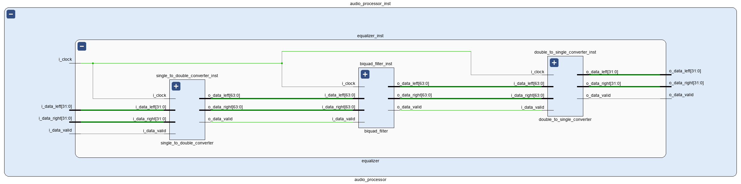
The Single to Double Converter module is based on the updated Fixed- to Floating-Point Converter module we explored last week and is shown below. The Double to Single Converter uses the same approach to perform the transformation in the opposite direction.
module single_to_double_converter # (
    parameter SP_FLOATING_POINT_BIT_WIDTH = 32,
    parameter DP_FLOATING_POINT_BIT_WIDTH = 64
    ) (
    input   logic                                       i_clock,
    // Audio Input
    input   logic                                       i_data_valid,
    input   logic   [SP_FLOATING_POINT_BIT_WIDTH-1 : 0] i_data_left,
    input   logic   [SP_FLOATING_POINT_BIT_WIDTH-1 : 0] i_data_right,
    // Audio Output
    output  logic                                       o_data_valid,
    output  logic   [DP_FLOATING_POINT_BIT_WIDTH-1 : 0] o_data_left,
    output  logic   [DP_FLOATING_POINT_BIT_WIDTH-1 : 0] o_data_right
);

    timeunit 1ns;
    timeprecision 1ps;

    // Single-to-double Conversion
    logic                                       single_to_double_valid_in;
    logic [SP_FLOATING_POINT_BIT_WIDTH-1 : 0]   single_to_double_data_in;
    logic                                       single_to_double_valid_out;
    logic [DP_FLOATING_POINT_BIT_WIDTH-1 : 0]   single_to_double_data_out;
    single_to_double single_to_double_inst (
        .aclk                   (i_clock),
        .s_axis_a_tvalid        (single_to_double_valid_in),
        .s_axis_a_tdata         (single_to_double_data_in),
        .m_axis_result_tvalid   (single_to_double_valid_out),
        .m_axis_result_tdata    (single_to_double_data_out)
    );

    // Single to Double FSM
    enum logic [1 : 0]  {IDLE,
                        CONVERT_LEFT_CHANNEL,
                        CONVERT_RIGHT_CHANNEL} single_to_double_fsm_state = IDLE;
    logic [SP_FLOATING_POINT_BIT_WIDTH-1 : 0] data_right = 'b0;

    always_ff @(posedge i_clock) begin : single_to_double_fsm
        case (single_to_double_fsm_state)
            IDLE : begin
                o_data_valid <= 1'b0;
                single_to_double_valid_in <= 1'b0;
                if (i_data_valid == 1'b1) begin
                    data_right <= i_data_right;
                    single_to_double_valid_in <= 1'b1;
                    single_to_double_data_in <= i_data_left;
                    single_to_double_fsm_state <= CONVERT_LEFT_CHANNEL;
                end
            end

            CONVERT_LEFT_CHANNEL : begin
                single_to_double_valid_in <= 1'b0;
                if (single_to_double_valid_out == 1'b1) begin
                    o_data_left <= single_to_double_data_out;
                    single_to_double_valid_in <= 1'b1;
                    single_to_double_data_in <= data_right;
                    single_to_double_fsm_state <= CONVERT_RIGHT_CHANNEL;
                end
            end

            CONVERT_RIGHT_CHANNEL : begin
                single_to_double_valid_in <= 1'b0;
                if (single_to_double_valid_out == 1'b1) begin
                    o_data_right <= single_to_double_data_out;
                    o_data_valid <= 1'b1;
                    single_to_double_fsm_state <= IDLE;
                end
            end

            default : begin
                single_to_double_fsm_state <= IDLE;
            end
        endcase
    end

endmodule
We will implement the Biquad Filter logic next week, for now the module will include a simple passthrough so we can make sure that all the other elements in our design work properly.
Simulation
We are now ready to create a testbench for our Equalizer module. We will use our trusty SystemVerilog WAVE File Reader, but before we setup our simulation we will update the WAVE reader so that it can be instantiated as a standalone module that outputs the audio stream with our data/data valid protocol. This will enable us to have smaller, cleaner testbenches for each module from now on, as shown below.
module tc_01();

    timeunit 1ns;
    timeprecision 1ps;

    logic clock;
    initial begin
        clock = 1'b0;
        forever begin
            #5ns;
            clock = ~clock;
        end
    end

    // WAVE File Reader
    logic           file_data_valid;
    logic [23 : 0]  file_data_left;
    logic [23 : 0]  file_data_right;
    wave_file_reader wave_file_reader_inst (
        .i_clock        (clock),
        .o_data_valid   (file_data_valid),
        .o_data_left    (file_data_left),
        .o_data_right   (file_data_right)
    );

    // Fixed-to-float Conversion - Left
    logic           fixed_to_float_left_valid;
    logic [31 : 0]  fixed_to_float_left_data;
    fixed_to_float fixed_to_float_left_inst (
        .aclk                   (clock),
        .s_axis_a_tvalid        (file_data_valid),
        .s_axis_a_tdata         (file_data_left),
        .m_axis_result_tvalid   (fixed_to_float_left_valid),
        .m_axis_result_tdata    (fixed_to_float_left_data)
    );

    // Fixed-to-float Conversion - Right
    logic           fixed_to_float_right_valid;
    logic [31 : 0]  fixed_to_float_right_data;
    fixed_to_float fixed_to_float_right_inst (
        .aclk                   (clock),
        .s_axis_a_tvalid        (file_data_valid),
        .s_axis_a_tdata         (file_data_right),
        .m_axis_result_tvalid   (fixed_to_float_right_valid),
        .m_axis_result_tdata    (fixed_to_float_right_data)
    );

    // Equalizer
    logic           equalizer_data_valid;
    logic [31 : 0]  equalizer_data_left;
    logic [31 : 0]  equalizer_data_right;
    equalizer # (
        .SP_FLOATING_POINT_BIT_WIDTH (32),
        .DP_FLOATING_POINT_BIT_WIDTH (64)
    ) equalizer_inst (
        .i_clock        (clock),
        .i_enable       (1'b1),
        // Audio Input
        .i_data_valid   (fixed_to_float_left_valid),
        .i_data_left    (fixed_to_float_left_data),
        .i_data_right   (fixed_to_float_right_data),
        // Audio Output
        .o_data_valid   (equalizer_data_valid),
        .o_data_left    (equalizer_data_left),
        .o_data_right   (equalizer_data_right)
    );

endmodule
The simulation results of our mono snare hit input are shown in the figure below. The analog waveforms are, from top to bottom (left channel only):
- The single-precision floating-point input of the Equalizer module
- The single-precision floating-point output of the Equalizer module
- The double-precision floating-point input of the Biquad Filter module
- The double-precision floating-point output of the Biquad Filter module
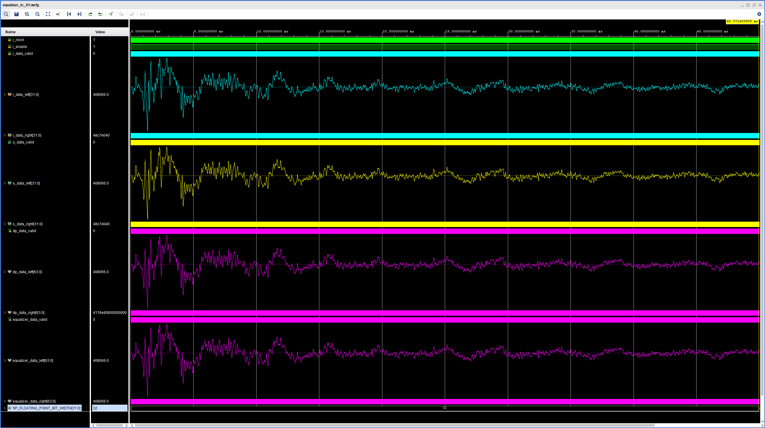
As we can see, the conversion takes place without issues in both directions. Generating the bitstream and downloading it to the ZedBoard confirmed that the passthrough works correctly on the hardware. We are now ready to start implementing the logic for our Biquad Filter module. See you next week!
Cheers,
Isaac
The RTL and simulation files for this post are available in the FPGA Audio Processor repository under this tag.