In this post we go over the architecture of an FPGA-based audio processor using the ZedBoard. The design will be entirely RTL-based, so we won’t be using the A9 processor on the Zynq for now.
The ZedBoard includes all the peripherals we need for audio processing. It has an ADAU1761 audio codec from Analog Devices and on-board connectors for mic in, line in, line out and headphone out. We will also use the buttons and switches to provide user input to our design, as well as the LEDs for visual feedback.
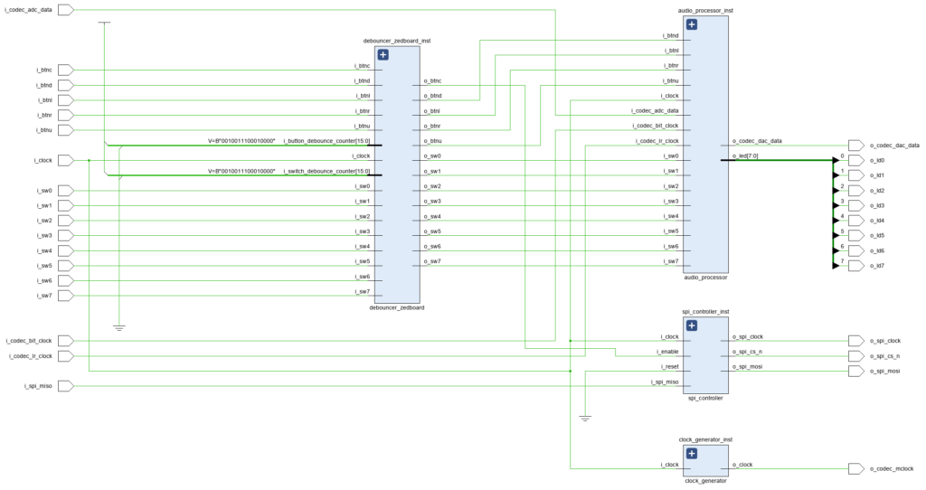
The top-level components of the ZedBoard Audio Processor are shown in Figure 1.
As we can see in Figure 1, there are four major components in the ZedBoard Audio Processor design:
- The Debouncer
- The Clock Generator
- The SPI Controller
- The Audio Processor
We will explore each component in detail in the next posts, for now we will focus on the design’s top level.
ZedBoard Audio Processor Top Level
The SystemVerilog description of the ZedBoard Audio Processor’s top level is shown below.
module fpga_audio_processor_top (
    // Clock
    input   logic i_clock,      // 100 MHz
    // Input switches
    input   logic i_sw0,
    input   logic i_sw1,
    input   logic i_sw2,
    input   logic i_sw3,
    input   logic i_sw4,
    input   logic i_sw5,
    input   logic i_sw6,
    input   logic i_sw7,
    // Input buttons
    input   logic i_btnu,
    input   logic i_btnd,
    input   logic i_btnl,
    input   logic i_btnr,
    input   logic i_btnc,
    // Output LEDs
    output  logic o_ld0,
    output  logic o_ld1,
    output  logic o_ld2,
    output  logic o_ld3,
    output  logic o_ld4,
    output  logic o_ld5,
    output  logic o_ld6,
    output  logic o_ld7,
    // SPI Interface
    output  logic o_spi_cs_n,
    output  logic o_spi_clock,
    output  logic o_spi_mosi,
    input   logic i_spi_miso,
    // Audio Codec
    input   logic i_codec_bit_clock,
    input   logic i_codec_lr_clock,
    input   logic i_codec_adc_data,
    output  logic o_codec_mclock,
    output  logic o_codec_dac_data
);

    timeunit 1ns;
    timeprecision 1ps;

    parameter SPI_CLOCK_DIVIDER_WIDTH = 5;
    parameter SPI_DATA_WIDTH = 32;

    // Debouncer Core
    logic sw0;
    logic sw1;
    logic sw2;
    logic sw3;
    logic sw4;
    logic sw5;
    logic sw6;
    logic sw7;
    logic btnu;
    logic btnd;
    logic btnl;
    logic btnr;
    logic btnc;

    debouncer_zedboard # (
        .SWITCH_COUNT           (8),
        .BUTTON_COUNT           (5),
        .DEBOUNCE_COUNTER_WIDTH (16)
    ) debouncer_zedboard_inst (
        // Clock
        .i_clock                    (i_clock),
        // Debounce counter values
        .i_switch_debounce_counter  (16\'d10000),
        .i_button_debounce_counter  (16\'d10000),
        // Input switches
        .i_sw0                      (i_sw0),
        .i_sw1                      (i_sw1),
        .i_sw2                      (i_sw2),
        .i_sw3                      (i_sw3),
        .i_sw4                      (i_sw4),
        .i_sw5                      (i_sw5),
        .i_sw6                      (i_sw6),
        .i_sw7                      (i_sw7),
        // Input buttons
        .i_btnu                     (i_btnu),
        .i_btnd                     (i_btnd),
        .i_btnl                     (i_btnl),
        .i_btnr                     (i_btnr),
        .i_btnc                     (i_btnc),
        // Debounced switch outputs
        .o_sw0                      (sw0),
        .o_sw1                      (sw1),
        .o_sw2                      (sw2),
        .o_sw3                      (sw3),
        .o_sw4                      (sw4),
        .o_sw5                      (sw5),
        .o_sw6                      (sw6),
        .o_sw7                      (sw7),
        // Debounced button outputs
        .o_btnu                     (btnu),
        .o_btnd                     (btnd),
        .o_btnl                     (btnl),
        .o_btnr                     (btnr),
        .o_btnc                     (btnc)
    );

    // SPI Controller
    spi_controller # (
        .SPI_CLOCK_DIVIDER_WIDTH    (SPI_CLOCK_DIVIDER_WIDTH),
        .SPI_DATA_WIDTH             (SPI_DATA_WIDTH)
    ) spi_controller_inst (
        // Clock, reset
        .i_clock        (i_clock),
        .i_reset        (1\'b0),
        // Control
        .i_enable       (btnc),
        // SPI interface
        .o_spi_cs_n     (o_spi_cs_n),
        .o_spi_clock    (o_spi_clock),
        .o_spi_mosi     (o_spi_mosi),
        .i_spi_miso     (i_spi_miso)
    );

    // Clock Generator
    clock_generator clock_generator_inst (
        .i_clock    (i_clock),
        .o_clock    (o_codec_mclock)
    );

    // Audio Processor
    audio_processor audio_processor_inst (
        .i_clock            (i_clock),
        // Audio Interface
        .i_codec_bit_clock  (i_codec_bit_clock),
        .i_codec_lr_clock   (i_codec_lr_clock),
        .i_codec_adc_data   (i_codec_adc_data),
        .o_codec_dac_data   (o_codec_dac_data),
        // Buttons
        .i_btnu             (btnu),
        .i_btnd             (btnd),
        .i_btnl             (btnl),
        .i_btnr             (btnr)
    );

endmodule
Clock and non-audio IO Signals
The ZedBoard Audio Processor uses the ZedBoard’s on-board 100 MHz oscillator, which is connected directly to the PL. This 100 MHz clock is used to a) drive the internal logic in the design, and b) generate the Master Clock signal that will be sent to the audio codec. The clock definition constraint used for this clock is shown below.
create_clock -period 10.000 -name i_clock -waveform {0.000 5.000} [get_ports i_clock]The buttons and switches on the ZedBoard are mapped to the top-level IO signals in our design. They are routed into the Debouncer module, which will generate bounce-free signals that we can safely use as input to our logic.
The LEDs are used for providing real-time visual feedback on the audio processing and analysis done in our logic, so they are connected to the Audio Processor core.
Audio Codec IO
The ADAU1761 audio codec has two separate interfaces: one for configuration/status, and one for sending and receiving audio data.
The audio codec supports I2C and SPI for configuration. The physical pins are shared between those interfaces, so only one can be used. Our design uses the SPI protocol (FPGA -> Master, audio codec -> Slave), and thus the top-level IO signals include the SPI Clock, Chip Select (CS) and Master-Output-Slave-Input (MOSI) outputs, as well as the Master-Input-Slave-Output (MISO) input.
Similarly, the audio codec supports several interfaces for sending and receiving audio data. Our design uses the default I2S mode with a bit clock, a left/right clock, one serial DAC data signal and one serial ADC data signal. Finally, a Master Clock signal is used to provide the core clock signal to the audio codec, which is generated in the Zynq from the on-board oscillator.
IO Constraints for the ZedBoard Audio Processor
Now that we have defined our top-level logical IO, we can map each signal to its corresponding FPGA pin. The pin names for the clock- and audio-related signals can be found in the ZedBoard Hardware User Guide. For the switches, buttons, and LEDs, the names are written directly on the PCB, which makes the mapping even easier. All the IO signals in our design use 3.3V. The IO constraints for the ZedBoard Audio Processor are shown below.
# Input Clock
set_property PACKAGE_PIN Y9 [get_ports i_clock]
set_property IOSTANDARD LVCMOS33 [get_ports i_clock]

# Input Switches
set_property PACKAGE_PIN F22 [get_ports i_sw0]
set_property IOSTANDARD LVCMOS33 [get_ports i_sw0]
set_property PACKAGE_PIN G22 [get_ports i_sw1]
set_property IOSTANDARD LVCMOS33 [get_ports i_sw1]
set_property PACKAGE_PIN H22 [get_ports i_sw2]
set_property IOSTANDARD LVCMOS33 [get_ports i_sw2]
set_property PACKAGE_PIN F21 [get_ports i_sw3]
set_property IOSTANDARD LVCMOS33 [get_ports i_sw3]
set_property PACKAGE_PIN H19 [get_ports i_sw4]
set_property IOSTANDARD LVCMOS33 [get_ports i_sw4]
set_property PACKAGE_PIN H18 [get_ports i_sw5]
set_property IOSTANDARD LVCMOS33 [get_ports i_sw5]
set_property PACKAGE_PIN H17 [get_ports i_sw6]
set_property IOSTANDARD LVCMOS33 [get_ports i_sw6]
set_property PACKAGE_PIN M15 [get_ports i_sw7]
set_property IOSTANDARD LVCMOS33 [get_ports i_sw7]

# Input Buttons
set_property PACKAGE_PIN P16 [get_ports i_btnc]
set_property IOSTANDARD LVCMOS33 [get_ports i_btnc]
set_property PACKAGE_PIN R16 [get_ports i_btnd]
set_property IOSTANDARD LVCMOS33 [get_ports i_btnd]
set_property PACKAGE_PIN N15 [get_ports i_btnl]
set_property IOSTANDARD LVCMOS33 [get_ports i_btnl]
set_property PACKAGE_PIN R18 [get_ports i_btnr]
set_property IOSTANDARD LVCMOS33 [get_ports i_btnr]
set_property PACKAGE_PIN T18 [get_ports i_btnu]
set_property IOSTANDARD LVCMOS33 [get_ports i_btnu]

# Output LEDs
set_property PACKAGE_PIN T22 [get_ports o_ld0]
set_property IOSTANDARD LVCMOS33 [get_ports o_ld0]
set_property PACKAGE_PIN T21 [get_ports o_ld1]
set_property IOSTANDARD LVCMOS33 [get_ports o_ld1]
set_property PACKAGE_PIN U22 [get_ports o_ld2]
set_property IOSTANDARD LVCMOS33 [get_ports o_ld2]
set_property PACKAGE_PIN U21 [get_ports o_ld3]
set_property IOSTANDARD LVCMOS33 [get_ports o_ld3]
set_property PACKAGE_PIN V22 [get_ports o_ld4]
set_property IOSTANDARD LVCMOS33 [get_ports o_ld4]
set_property PACKAGE_PIN W22 [get_ports o_ld5]
set_property IOSTANDARD LVCMOS33 [get_ports o_ld5]
set_property PACKAGE_PIN U19 [get_ports o_ld6]
set_property IOSTANDARD LVCMOS33 [get_ports o_ld6]
set_property PACKAGE_PIN U14 [get_ports o_ld7]
set_property IOSTANDARD LVCMOS33 [get_ports o_ld7]

# SPI
set_property PACKAGE_PIN AB4 [get_ports o_spi_clock]
set_property IOSTANDARD LVCMOS33 [get_ports o_spi_clock]
set_property PACKAGE_PIN AB1 [get_ports o_spi_cs_n]
set_property IOSTANDARD LVCMOS33 [get_ports o_spi_cs_n]
set_property PACKAGE_PIN Y5 [get_ports o_spi_mosi]
set_property IOSTANDARD LVCMOS33 [get_ports o_spi_mosi]
set_property PACKAGE_PIN AB5 [get_ports i_spi_miso]
set_property IOSTANDARD LVCMOS33 [get_ports i_spi_miso]

# Audio Codec
set_property PACKAGE_PIN AA6 [get_ports i_codec_bit_clock]
set_property IOSTANDARD LVCMOS33 [get_ports i_codec_bit_clock]
set_property PACKAGE_PIN Y6 [get_ports i_codec_lr_clock]
set_property IOSTANDARD LVCMOS33 [get_ports i_codec_lr_clock]
set_property PACKAGE_PIN AA7 [get_ports i_codec_adc_data]
set_property IOSTANDARD LVCMOS33 [get_ports i_codec_adc_data]
set_property PACKAGE_PIN AB2 [get_ports o_codec_mclock]
set_property IOSTANDARD LVCMOS33 [get_ports o_codec_mclock]
set_property PACKAGE_PIN Y8 [get_ports o_codec_dac_data]
set_property IOSTANDARD LVCMOS33 [get_ports o_codec_dac_data]
In the next post we’ll focus on the debouncer logic for the switches and buttons on the ZedBoard.
Cheers,
Isaac


One response to “001 – ZedBoard Audio Processor”
It’s Extremely helpful resource. Thanks a lot brother.