In this post we will go over the implementation of a mono delay effect for our FPGA Audio Processor.
The delay is one of the most frequently used effects in music and audio production. The basic principle of a delay effect is to store audio samples and play them back later. In our previous post we used this principle to create a trivially simple delay – one so simple that the effect was inaudible. In today’s post we will expand on that principle to create a functional mono delay.
Feedforward and Feeback Delay Architectures
There are two ways in which we can delay the audio samples to achieve our delay effect: feedforward and feedback. In a feedforward architecture the incoming samples are delayed and added to the output as shown in the figure below.
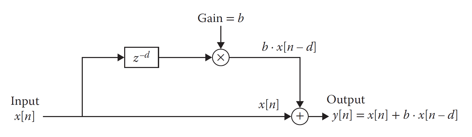
The feedforward architecture generates a single-tap delay, that is, each input sample is played twice: once in real time and once delayed. It is also common, though not strictly necessary, to apply a gain factor to the delayed sample before adding it to the current one.
In a feedback architecture, the outgoing samples are delayed and added to the inputs, as shown in the figure below.
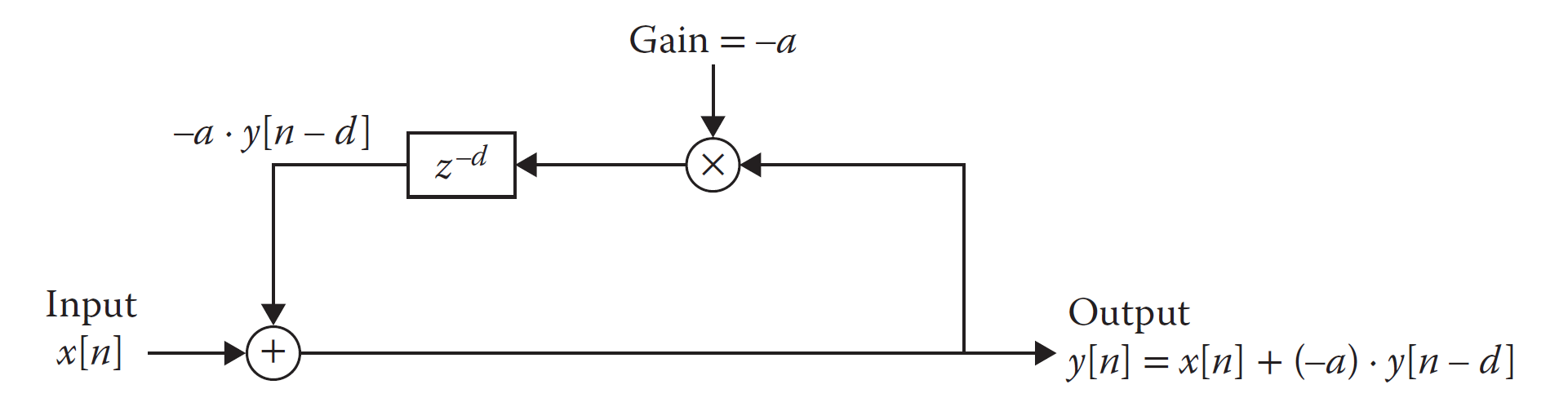
In theory, the feedback architecture generates an infinite number of taps, that is, each sample could be played an infinite number of times. Like in the feedforward architecture, there is also a gain applied to the delayed samples, but in the case of a feedback delay this gain is not optional. Moreover, it is critical that this gain is smaller than unity to guarantee that the output decays over time. Setting the gain to unity or higher would cause a positive feedback loop in which the outgoing samples get infinitely larger with each iteration.
By setting the feedback gain smaller than unity, we guarantee that the value of the delayed samples decays over time. In theory, this means that a sample will never be zero, it would just get smaller and smaller without quite reaching zero. In practice, the delayed samples become so small that they we can’t hear them, or our processing system can’t represent them with enough accuracy, so it just sets them to zero.
Circular Buffer
When creating an audible delay effect, we need to make sure that the time between playing the real-time sample and the delayed sample is long enough, otherwise we will not be able to hear them as two separate samples. Most literature puts this threshold at about 40 ms, but most practical delay effects must support at least a few hundred milliseconds, many support even several seconds.
This means that we need to come up with a structure that will allow us to always store the last few hundred milliseconds worth of audio samples. For a sample rate of 44.1 kHz, this means 4.410 samples for each 100 ms. For this we will use a circular buffer, as shown in the figure below.
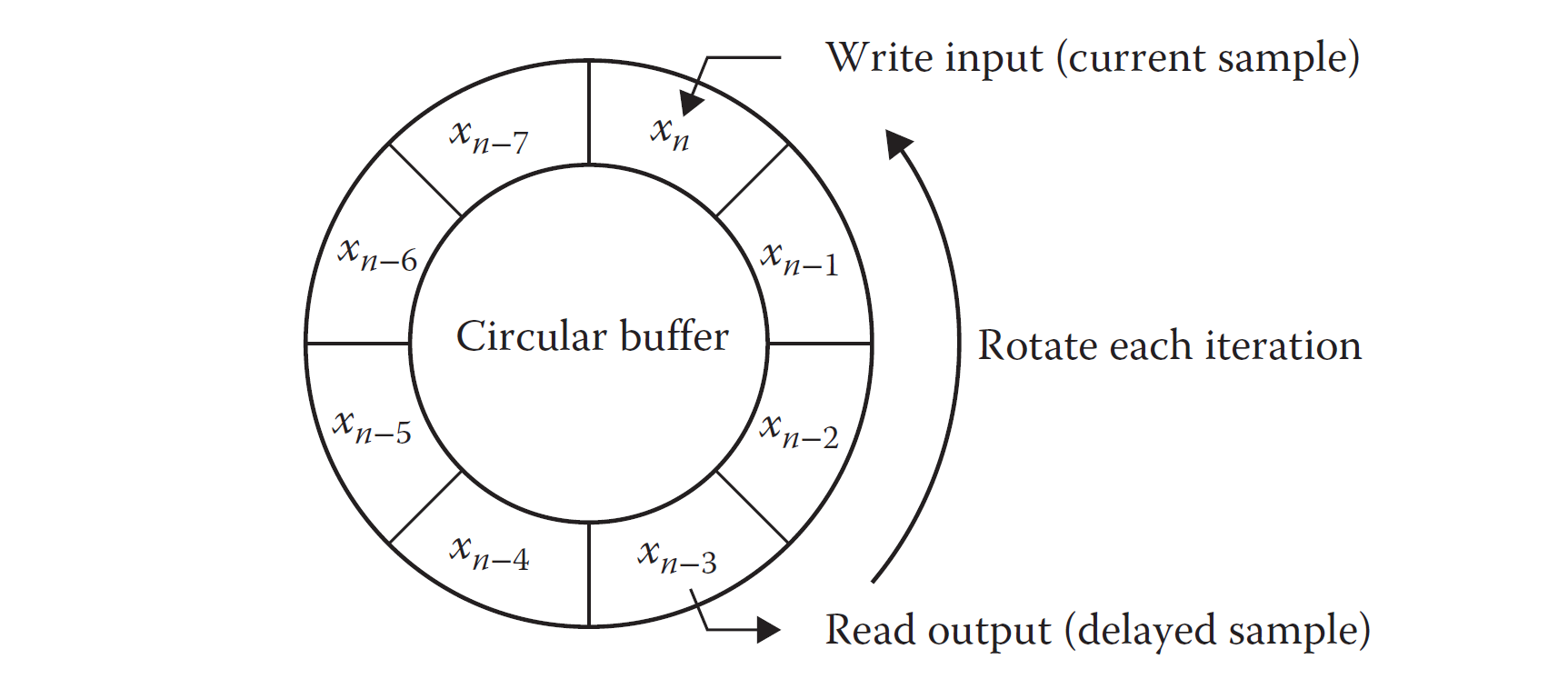
A circular buffer has separate write and read pointers. At each audio sampling event the incoming (feedforward) or outgoing (feedback) sample is written to the buffer address indicated by the write pointer. At the same sampling event a delayed audio sample is read from the buffer address indicated by the read pointer. At each sampling event both pointers are incremented by one.
The maximum size of the buffer and the sampling rate determine the maximum delay time that we can reproduce. A buffer size of 16384 samples at a sampling rate of 44.1 kHz will gives a maximum delay time of about 372 ms.
For our delay we initialize the write pointer to 0 and the read pointer to 1. These absolute values are not critical, what’s important is that the read pointer always stays one address ahead of the write pointer. Thus, we initialize the write and read pointer to 0 and 1 respectively and increment them together with each audio sample.
We adjust the delay time by setting maximum values for the write and read pointers. Once these maximum values are reached, the counters are set to zero, which produces the circular behavior we want for our buffer. For example, initializing the write pointer to 8191 and the read pointer to 8192 (it must always be one address ahead!) will give us a delay of about 186 ms at 44.1 kHz.
Putting Together our Mono Delay
In addition to our custom logic, we will need four IP cores to build our mono Delay: one Block RAM (BRAM) for our circular buffer and floating-point operators for addition, division, and multiplication. The addition and division are required for converting our stereo signal to mono, while the addition and multiplication are required for the delay itself.
Our custom logic is implemented in a state machine, which performs the following tasks:
- Increment the write and read pointers when a new sample from the ADC arrives
- Add both channels of the incoming samples together
- Divide the added samples by two, thus completing the conversion from stereo to mono. For a forward delay this is when the mono sample is written to the circular buffer
- Apply the delay gain to the delayed sample
- Add the delayed sample to the real-time sample and generate the output. For a feedback delay this is when the output sample is written to the circular buffer
The complete code for our mono Delay is shown below.
module delay #(
    parameter string FEED_TYPE = "FEEDFORWARD"     // "FEEDBACK", "FEEDFORWARD"
    )(
    input   logic           i_clock,
    input   logic [31 : 0]  i_data_left,
    input   logic [31 : 0]  i_data_right,
    input   logic           i_data_valid,
    output  logic [31 : 0]  o_data_left,
    output  logic [31 : 0]  o_data_right,
    output  logic           o_data_valid
);

    logic           fp_adder_valid_out;
    logic [31 : 0]  fp_adder_data_out;
    logic [31 : 0]  fp_adder_data_a_in;
    logic [31 : 0]  fp_adder_data_b_in;
    logic           fp_adder_data_valid;
    fp_adder fp_adder_inst(
        .aclk                   (i_clock),
        .s_axis_a_tvalid        (fp_adder_data_valid),
        .s_axis_a_tdata         (fp_adder_data_a_in),
        .s_axis_b_tvalid        (fp_adder_data_valid),
        .s_axis_b_tdata         (fp_adder_data_b_in),
        .m_axis_result_tvalid   (fp_adder_valid_out),
        .m_axis_result_tdata    (fp_adder_data_out)
    );

    logic           fp_divider_valid_out;
    logic [31 : 0]  fp_divider_data_out;
    logic [31 : 0]  fp_divider_data_a_in;
    logic [31 : 0]  fp_divider_data_b_in;
    logic           fp_divider_data_valid;
    fp_divider fp_divider_inst(
        .aclk                   (i_clock),
        .s_axis_a_tvalid        (fp_divider_data_valid),
        .s_axis_a_tdata         (fp_divider_data_a_in),
        .s_axis_b_tvalid        (fp_divider_data_valid),
        .s_axis_b_tdata         (fp_divider_data_b_in),
        .m_axis_result_tvalid   (fp_divider_valid_out),
        .m_axis_result_tdata    (fp_divider_data_out)
    );

    logic           fp_mult_valid_out;
    logic [31 : 0]  fp_mult_data_out;
    logic [31 : 0]  fp_multiplier_data_a_in;
    parameter logic [31 : 0]  feedback_gain = 31\'b00111111010000000000000000000000;     // 0.75
    logic           fp_multiplier_data_valid;
    logic           fp_multiplier_data_valid_pre_delay;
    logic           fp_multiplier_data_valid_pre_delay_2;
    fp_multiplier fp_multiplier_inst(
        .aclk                   (i_clock),
        .s_axis_a_tvalid        (fp_multiplier_data_valid),
        .s_axis_a_tdata         (fp_multiplier_data_a_in),
        .s_axis_b_tvalid        (fp_multiplier_data_valid),
        .s_axis_b_tdata         (feedback_gain),
        .m_axis_result_tvalid   (fp_mult_valid_out),
        .m_axis_result_tdata    (fp_mult_data_out)
    );

    logic           delay_buffer_wr_en;
    logic [13 : 0]  delay_buffer_addra = \'b0;
    logic [31 : 0]  delay_buffer_dina;
    logic [13 : 0]  delay_buffer_addrb = 14\'d1;
    logic [31 : 0]  delay_buffer_douta;
    delay_circular_buffer delay_circular_buffer_inst(
        .clka   (i_clock),
        .wea    (delay_buffer_wr_en),
        .addra  (delay_buffer_addra),
        .dina   (delay_buffer_dina),
        .clkb   (i_clock),
        .addrb  (delay_buffer_addrb),
        .doutb  (delay_buffer_douta)
    );

    // Main FSM
    enum logic [2 : 0]  {IDLE,
                        ADD_INCOMING_SAMPLES,
                        DIVIDE_ADDED_SAMPLES,
                        APPLY_DELAY_GAIN,
                        GENERATE_OUTPUT} fsm_state = IDLE;
    logic [31 : 0] current_mono_sample;

    always_ff @(posedge i_clock) begin
            fp_multiplier_data_valid_pre_delay_2 <= fp_multiplier_data_valid_pre_delay;
            fp_multiplier_data_valid <= fp_multiplier_data_valid_pre_delay_2;
        case (fsm_state)
            IDLE : begin
                fp_adder_data_valid <= 1\'b0;
                fp_divider_data_valid <= 1\'b0;
                fp_multiplier_data_valid_pre_delay <= 1\'b0;
                delay_buffer_wr_en <= 1\'b0;
                o_data_valid <= 1\'b1;
                if (i_data_valid == 1\'b1) begin
                    fp_adder_data_a_in <= i_data_left;
                    fp_adder_data_b_in <= i_data_right;
                    fp_adder_data_valid <= 1\'b1;
                    delay_buffer_addra <= delay_buffer_addra + 1;
                    delay_buffer_addrb <= delay_buffer_addrb + 1;
                    fsm_state <= ADD_INCOMING_SAMPLES;
                end
            end

            ADD_INCOMING_SAMPLES : begin
                fp_adder_data_valid <= 1\'b0;
                if (fp_adder_valid_out == 1\'b1) begin
                    fp_divider_data_a_in <= fp_adder_data_out;
                    fp_divider_data_b_in <= 32\'h40000000;    // 2
                    fp_divider_data_valid <= 1\'b1;
                    fsm_state <= DIVIDE_ADDED_SAMPLES;
                end
            end

            DIVIDE_ADDED_SAMPLES : begin
                fp_divider_data_valid <= 1\'b0;
                if (fp_divider_valid_out == 1\'b1) begin
                    current_mono_sample <= fp_divider_data_out;
                    if (FEED_TYPE == "FEEDFORWARD") begin
                        delay_buffer_dina <= fp_adder_data_out;
                        delay_buffer_wr_en <= 1\'b1;
                    end
                    fp_multiplier_data_valid_pre_delay <= 1\'b1;
                    fsm_state <= APPLY_DELAY_GAIN;
                end
            end

            APPLY_DELAY_GAIN : begin
                delay_buffer_wr_en <= 1\'b0;
                fp_multiplier_data_valid_pre_delay <= 1\'b0;
                fp_multiplier_data_a_in <= delay_buffer_douta;
                if (fp_mult_valid_out == 1\'b1) begin
                    fp_adder_data_a_in <= fp_mult_data_out;
                    fp_adder_data_b_in <= current_mono_sample;
                    fp_adder_data_valid <= 1\'b1;
                    fsm_state <= GENERATE_OUTPUT;
                end
            end

            GENERATE_OUTPUT : begin
                fp_adder_data_valid <= 1\'b0;
                if (fp_adder_valid_out == 1\'b1) begin
                    o_data_left <= fp_adder_data_out;
                    o_data_right <= fp_adder_data_out;
                    o_data_valid <= 1\'b1;
                    if (FEED_TYPE == "FEEDBACK") begin
                        delay_buffer_dina <= fp_adder_data_out;
                        delay_buffer_wr_en <= 1\'b1;
                    end
                    fsm_state <= IDLE;
                end
            end

            default : begin
                fsm_state <= IDLE;
            end
        endcase
    end

endmodule
One pattern that might be confusing when analyzing the FSM is how the floating-point operations are controlled. Let’s take the Add Incoming Samples state: in this state the FSM waits for the addition of the incoming samples to be finished, but the addition process was started when the FSM was coming out of the Idle state. In a similar way, the Divide Added Samples state waits for the division of the added samples to be finished, but the division was started when the FSM was coming out of the Add Incoming Samples state. This might seem counter-intuitive, but it avoids the need for additional storage of the result of the floating-point operations.
Simulation
We are now ready to simulate our mono delay. We will use a snare hit to help visualize it better in the waveforms. First let’s take a look at the feedforward delay, shown in the figure below.
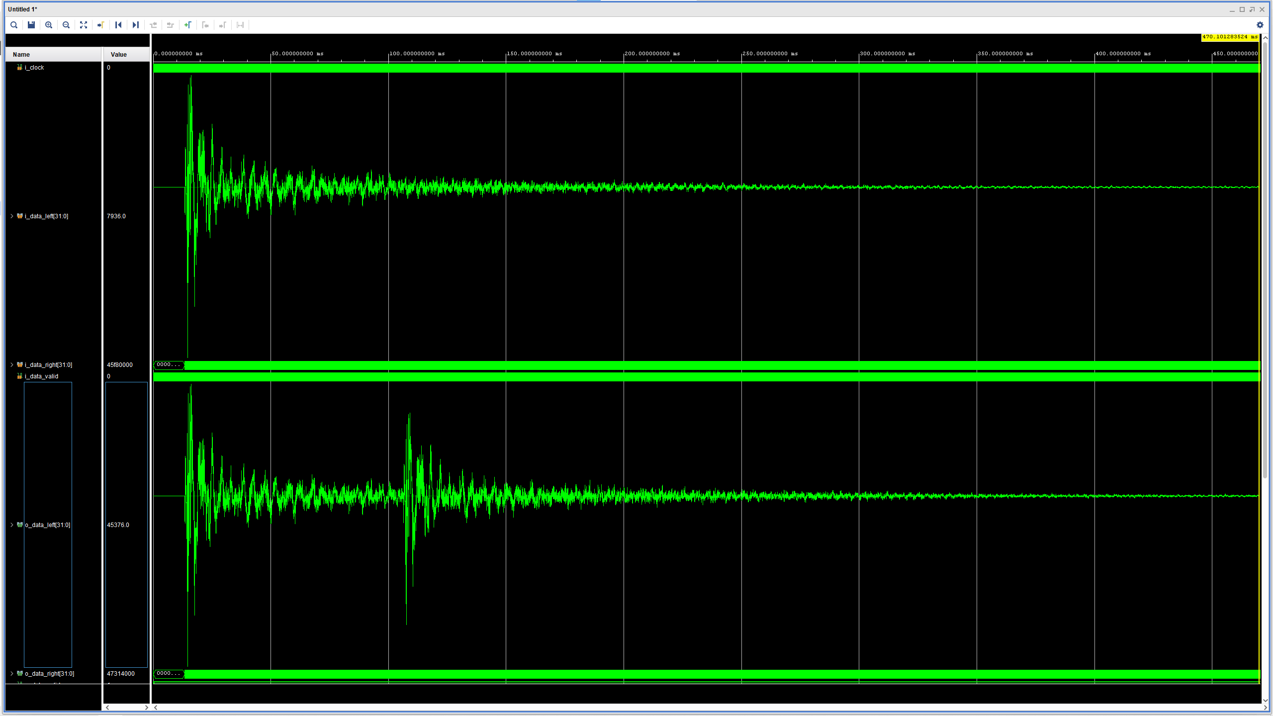
As expected, we can see that for a single snare hit at the input we see two at the output: the first is the real-time sample, the second is the delayed sample. In this simulation the maximum value of the write pointer has been set to 2047, and the maximum value of the read pointer has been set to 2048, thus providing a delay time of about 93 ms.
The feedback delay is shown in the figure below.
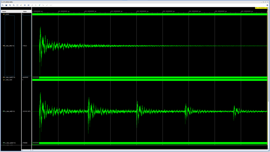
Here we can see the multiple taps appearing at the output at the set delay time (~93 ms). Because the feedback gain has been set to 0.75, the delayed samples become smaller with each iteration and will eventually reach zero.
Cheers,
Isaac