In this post we will run C Synthesis and Co-Simulation for our dBFS Converter module. We will also discuss how to export the dBFS Converter from Vitis HLS and make it available for our Zynq Audio Processor project in Vivado.
In the previous post we examined the input files required for a Vitis HLS project and introduced the four major steps in the Vitis HLS workflow. We then performed the first of those, C Simulation. In this post we will perform the other three (C Synthesis, Co-Simulation, RTL Export) and will add the exported IP to the repository of our Audio Processor project in Vivado.
C Synthesis
In the C Synthesis step Vitis HLS converts our C/C++ function to synthesizable RTL. We can start the C Synthesis from the ‘Run’ drop-down menu in the Vitis HLS Workspace. When the C Synthesis is completed the Synthesis Summary Report in the Synthesis View is displayed, as shown in the figure below.
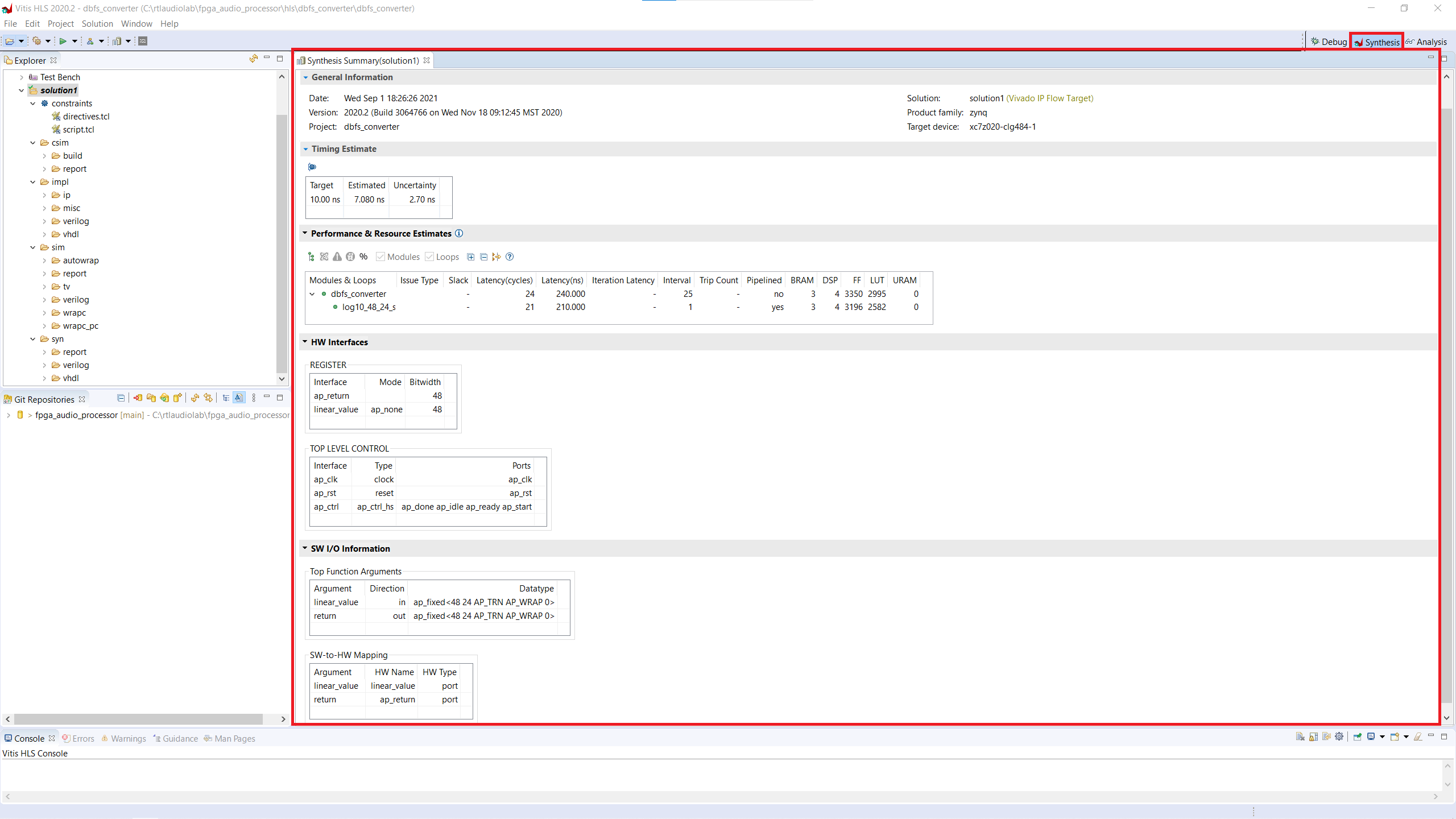
The Synthesis Summary Report has five sections:
- The General Information section contains the date, version, and name of the project, as well as the name of the solution, the product family, and the target device.
- The Timing Estimate section displays the target timing period (10 ns) the estimated period for the generated solution (7.080 ns) and the uncertainty left as a safety margin for the downstream tools (2.7 ns. Because we didn’t specify an uncertainty, Vitis HLS defaults to 27% of the target period).
- The Performance and Resource Estimates section contains the main performance parameters of a Vitis HLS solution. Since the dBFS Converter operates on scalar values, there is no iteration latency or trip count. In this section we can also find estimates for the utilization of FPGA resources. These estimates are not final, the exact resource utilization is only known after performing synthesis and implementation. In fact, the resource utilization estimates in Vitis HLS can be very inaccurate, so it’s better not to rely on them.
- The HW Interfaces section contains the IO data registers in the synthesized dBFS Converter, as well as the top-level control ports added by Vitis HLS, namely
- ap_clock: input clock.
- ap_reset: input reset.
- ap_done: output, stays high for one cycle of ap_clk to indicate that the dBFS Converter has completed its calculation and the data returned is valid.
- ap_idle: output, indicates that the dBFS Converter is not processing any data.
- ap_ready: output, indicates that the dBFS Converter is ready to accept new inputs.
- ap_start: input, it commands the dBFS Converter to start a new calculation using the current input values.
- The SW IO Information section contains the arguments of our C/C++ function and describes how they have been mapped to the top-level IO signals in hardware.
Co-Simulation
In the Co-Simulation step Vitis HLS runs our testbench once again, but instead of using our C/C++ description of the dBFS Converter, it calls the RTL description that was generated in the C Synthesis step. The Co-Simulation can be started from the ‘Run’ drop-down menu of the Vitis HLS workspace, which opens the C/RTL Co-Simulation Dialog as shown in the figure below.
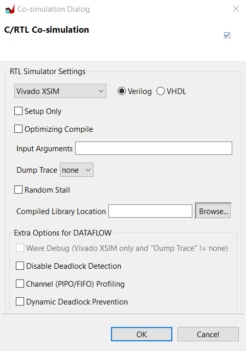
In the C/RTL Co-Simulation dialog we can choose several simulation parameters, like the target language and Simulator. We will use the default settings and click ‘Ok’ to start the Co-Simulation. The Co-Simulation results are shown in the figure below.
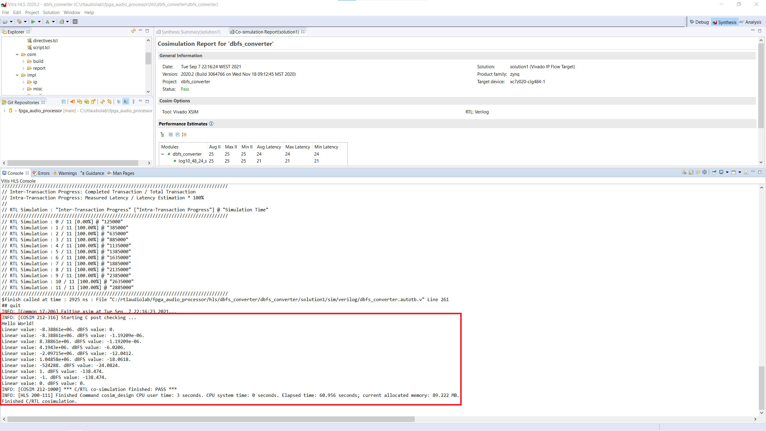
Depending on the checking strategy we choose, the Co-Simulation results may deviate from the C Simulation results, so we need to account for this when writing a self-checking testbench. Because we are not using a separate reference model or external reference values in our testbench, we expect to get the exact same results as with the C Simulation, which is the case here.
Export RTL
In the Export RTL step Vitis HLS generates a representation of our dBFS Converter that can be imported into an implementation toolchain, in our case, Vivado. We can start the RTL Export from the ‘Run’ drop-down menu of the Vitis HLS workspace. The ‘Export RTL as IP’ dialog pops up, as shown in the figure below.

By leaving all the default options and indicating a destination folder we can export our HLS-generated IP core as a zip file.
Vivado Integration
After exporting it as a zip file, we will take two steps to make our dBFS Converter IP core available in our Audio Processor project. First, we need to store the contents of the zip file generated by Vits HLS in the IP folder of our Vivado project. Unlike built-in Vivado IP cores which only requires us to store the XCI file, we need to store all the file and folders generated by Vitis HLS. I like to create an HLS folder within the project’s IP folder. This way I can store each HLS IP in its own subfolder, and thus keep the hierarchical levels consistent.
The second step for making our dBFS Converter IP available in our Vivado project is to add the HLS IP folder to the project’s IP repository. This can be done in the project settings, and after doing this we can find and instantiate our dBFS Converter IP from the IP Catalog like any other built-in Vivado IP core.
In the next and final part of this series we will instantiate, simulate, and implement our dBFS Converter HLS IP core within the LED Meter in our audio processor.
Cheers,
Isaac