In this post we will update our LED Meter to add support for stereo display and a visual overflow alarm.
A while ago we discussed the implementation of an LED Meter, which mapped the value of each audio sample going out of our Audio Processor to the LEDs on the ZedBoard. We then expanded it to perform a C-based linear-to-dBFS conversion of the audio samples on the FPGA using an HLS-based IP core. We will now update the LED Meter logic by adding support for stereo metering, making the LEDs blink when the audio samples exceed a maximum threshold, and removing the linear-to-dBFS conversion.
Stereo Metering
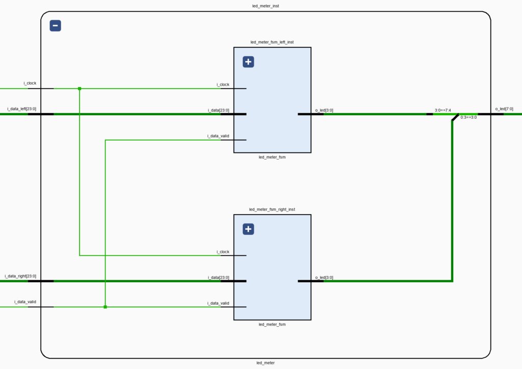
When moving from mono to stereo metering the channels are measured independently, so we don’t need to extract a mono value for each incoming sample. One way to do this is by encapsulating the single-channel metering on its own LED Meter FSM module and instantiating it once for each channel within the LED Meter module, as shown in the figure below.
This approach is elegant and scalable: the metering logic is separated into independent modules and we can add channels by creating new instances. It is also very fast, as both channels are metered in parallel in a fraction of the sampling rate. However, the resource utilization could be kept almost constant – even when working with multichannel audio – by reusing the metering logic for several channels. Because the channels would be metered one after the other, this approach would be much slower than the fully parallel version, but it will still be fast enough for most use cases. We won’t do that here because, as we’ll see later, the LED Meter FSM logic uses a negligible fraction of the resources on our Zynq, but logic reuse for multichannel audio processing is an important design pattern that we should keep in mind for real-world designs. I’ll make sure to preach it every now and then, even though it does not play a significant role for this project.
Overflow Alarm
One useful feature in an audio LED Meter is the ability to indicate when an audio sample overflows, or even when it is close to overflowing. We can do this by adding logic so that our LED Meter reacts differently when the absolute value of the audio sample is above a certain threshold. For a strict overflow detection, we would set this threshold to the maximum value that can be represented by our audio codec, 8.388.607, equivalent to about 0 dBFS (on the negative side). We’ll use a more conservative value of 7.919.356, roughly -0.5 dBFS.
Now, how should our LED Meter behave when the audio sample is greater than our threshold? A common way to deal with this is to make an LED sticky, that is, an overflow LED is turned on and remains on until the user dismisses it. To minimize user interaction we’ll have all four LEDs for the overflowing channel blink four times, for a total of 1.4 seconds. This should be enough to get the operator’s attention.
The complete code for the LED Meter FSM is shown below.
module led_meter_fsm (
    input   logic i_clock,
    // Audio Input
    input   logic signed    [23 : 0]    i_data,
    input   logic                       i_data_valid,
    // LED Meter Output
    output  logic           [3 : 0]     o_led
);

    timeunit 1ns;
    timeprecision 1ps;

    logic [3 : 0] led;
    logic signed [23 : 0] audio_sample;
    logic [27 : 0] overflow_counter;

    // Main FSM
    enum logic [1 : 0]  {IDLE,
                        GET_ABS_VALUE,
                        UPDATE_LED,
                        OVERFLOW} main_fsm_state = IDLE;

    always_ff @(posedge i_clock) begin : main_fsm
        case (main_fsm_state)
            IDLE : begin
                overflow_counter <= 'b0;
                if (i_data_valid == 1'b1) begin
                    audio_sample <= i_data;
                    main_fsm_state <= GET_ABS_VALUE;
                end
            end

            GET_ABS_VALUE : begin
                if (audio_sample[$left(audio_sample)] == 1'b1) begin      // Negative value, need to convert to positive
                    audio_sample <= (~audio_sample) + 1;
                end
                main_fsm_state <= UPDATE_LED;
            end

            UPDATE_LED : begin
                main_fsm_state <= IDLE;
                if (audio_sample > 7919356) begin  // ~-0.5 dBFS
                    main_fsm_state <= OVERFLOW;
                    led <= 'b1111;
                end else if (audio_sample > 4194304) begin  // ~-6 dBFS
                    led <= 4'b1111;
                end else if (audio_sample > 2097152) begin  // ~-12 dBFS
                    led <= 4'b0111;
                end else if (audio_sample > 1048576) begin  // ~-24 dBFS
                    led <= 4'b0011;
                end else if (audio_sample > 524288) begin   // ~-48 dBFS
                    led <= 4'b0001;
                end else begin
                    led <= 4'b0000;
                end
            end

            OVERFLOW : begin
                overflow_counter <= overflow_counter + 1;
                if  ((overflow_counter == 20000000) ||
                    (overflow_counter == 40000000) ||
                    (overflow_counter == 60000000) ||
                    (overflow_counter == 80000000) ||
                    (overflow_counter == 100000000) ||
                    (overflow_counter == 120000000)) begin
                    led <= ~led;
                end
                if (overflow_counter == 140000000) begin
                    led <= 'b0;
                    main_fsm_state <= IDLE;
                end
            end

            default : begin
                main_fsm_state <= IDLE;
            end
        endcase
    end
    assign o_led = led;

endmodule
LED Mapping
Because the LEDs on the ZedBoard are layed out horizontally, we’ll set up the output of the stereo LED Meter so that the LEDs assigned to the lowest peak values are in the center, and the LEDs assigned to the highest peak values are on the sides. The left channel meter will be mapped to the four LEDs on the left (LED7 – LD4), while the right channel meter will be mapped to the four LEDs on the right (LED3 – LED0). This mapping and the instantiation of the LED Meter FSM module for each channel is done in the LED Meter module, shown below.
module led_meter (
    input   logic i_clock,
    // Audio Input
    input   logic signed [23 : 0]   i_data_left,
    input   logic signed [23 : 0]   i_data_right,
    input   logic                   i_data_valid,
    // LED Meter Output
    output  logic [7 : 0]   o_led
);

    timeunit 1ns;
    timeprecision 1ps;

    led_meter_fsm led_meter_fsm_left_inst (
    .i_clock        (i_clock),
    // Audio Input
    .i_data         (i_data_left),
    .i_data_valid   (i_data_valid),
    // LED Meter Output
    .o_led          (o_led[7 : 4])
    );

    logic [3 : 0] aux;
    led_meter_fsm led_meter_fsm_right_inst (
    .i_clock        (i_clock),
    // Audio Input
    .i_data         (i_data_right),
    .i_data_valid   (i_data_valid),
    // LED Meter Output
    .o_led          (aux)
    );

    // Maps the right channel LEDs so the highest sample value is shown on the right
    assign aux[0] = o_led[3];
    assign aux[1] = o_led[2];
    assign aux[2] = o_led[1];
    assign aux[3] = o_led[0];

endmodule
Resource Utilization
The resource utilization of the stereo LED Meter is shown in Figure 2 below.
As you can see, even duplicating the metering logic does not amount to even 0.8% of any of the available resources on the Zynq. This is a stark contrast when compared with the previous implementation, which used an HLS-based IP core to convert the audio sample values from the linear scale to dBFS on the FPGA fabric. As we discussed in the last part of that series, it makes more sense to convert the threshold values from dBFS to the linear scale in some other fashion (at compile time or in software at runtime), so that the LED Meter only uses FPGA resources to make the comparison between the audio sample and the different thresholds.
Bypass Switch
One more thing before we wrap things up: when testing the Stereo LED Meter it became evident how much the delay logic increases the amplitude of the outgoing signal. Bypassing the delay would be helpful to get a sense of the maximum amplitude that the input audio signal can have before the alarms in the LED Meter go off. It was therefore a good opportunity to add a useful feature: an ‘enable’ switch. From now on, whenever the SW0 switch on the ZedBoard is on, our Stereo Delay will be engaged, otherwise it will simply pass its inputs through to its outputs. We will include an enable switch for some of the audio-processing modules that will be added later.
In the next post we will implement a different strategy to measure the amplitude of an audio signal, the root mean square (RMS).
Cheers,
Isaac


